RLC serial circuit


Let's consider a circuit in which a resistor (R) - an inductor (L) - a capacitor (C) are connected in series.
Every moment, the current through the circuit is the same at every point. (It is important, so remember it.)
Although the current is totally constant, the height of the voltage applied to each part is different.
The voltage formed in the inductor is due to counter electromotive force. For AC sinusoidal wave, the back electromotive force already becomes the maximum value when current is the steepest point. Therefore, the electromotive force induced in the inductor goes 90° earlier than the current.
Capacitors are slightly different from inductors. The voltage formed on the capacitor is that electric charge builds up in the capacitor. In the AC sinusoidal wave, when the maximum amount of electric charge accumulates in the capacitor, it becomes immediately before the direction of the current changes. Therefore, the voltage of the capacitor is 90° delayed along with the current.
When the inductor and the capacitor are connected in series, the voltage induced in the inductor and the voltage charged in the capacitor is 180° opposite with each other.
Resonance frequency
The inductive reactance of the inductor (the role of the resistance of the DC circuit) and the capacitive reactance of the capacitor (the role of the DC circuit's resistance) are 180 ° opposite each other in the case of voltage.
In the case of a circuit in which an inductor and a capacitor are connected in series, it is necessary to calculate the AC impedance by summing the phase vectors relation rather than simply summing.
The impedance, which acts as a resistance in the AC circuit is,
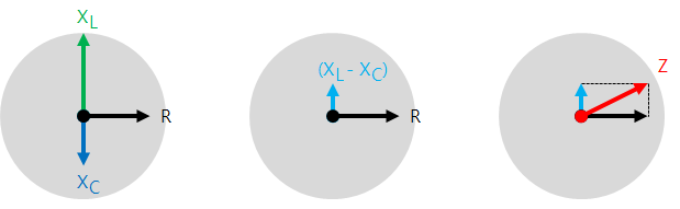
\[ Z=\sqrt { { R }^{ 2 }+{ ({ X }_{ L }-{ X }_{ C }) }^{ 2 } } \]
The impedance is the same as the length of the hypotenuse of the right triangle with the base and height of the reactance difference (XL - XC) and general resistance value 'R.'
Because the inductor and the capacitor phase are opposite each other, adjusting the AC power supply frequency can minimize the circuit's resistance. In other words, equalize the inductive reactance and the capacitance reactance.
\[ X_L = X_C \]
If so, it will be done,
\[ 2\pi fL=\frac { 1 }{ 2\pi fC } \]
\[ f=\frac { 1 }{ 2\pi \sqrt { LC } } \]
This frequency is called the resonance frequency (natural frequency).
In this case, because the inductive reactance and capacitive reactance are canceled, the circuit current is only the resistance effect.
Since the inductive reactance and capacitive reactance are different depending on the frequency, the current value also varies.
In other words, using the RLC circuit, you can select only the current of the desired frequency. This method is widely used for radio and wireless communication circuits.
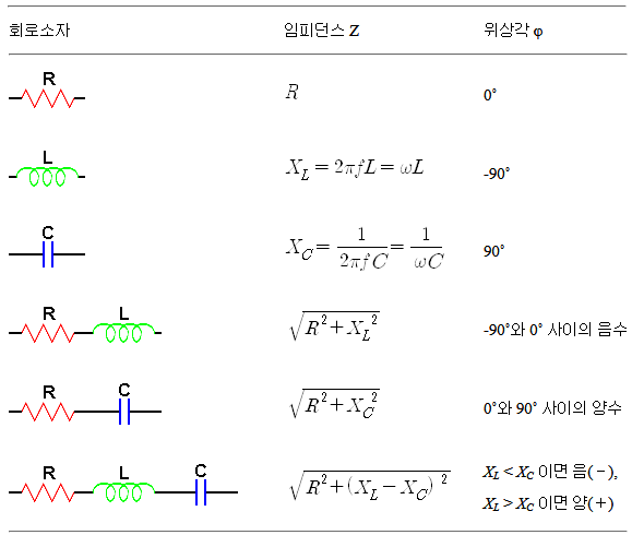
Impedance value and phase angle of series circuit consisting of collation of various circuit elements