High frequency alternating currents are difficult to pass through the inductor.
 An inductor is a part made by winding a wire.
In the case of direct current, the inductor only works as a lead.
When an AC voltage is applied to this inductor, the inductor acts like a resistor.
When the current in the inductor changes, an electromotive force is generated that interrupts the current.
The inductor’s behavior as a resistor is proportional to its inductance(L) and frequency(f).
The current in the inductor ‘I’ is
\[I\quad =\quad \frac { V }{ \omega L } \quad =\quad \frac { V }{ 2\pi fL } \]
ω = frequency
V = AC voltage
L = self induction coefficient
At this time, ‘\( 2 \pi fL \)’ which acts as a resistor of a DC circuit, is called inductive reactance.
It is expressed as XL, and its unit is Ω.
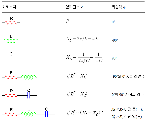
\[{ X }_{ L }\quad =\quad 2\pi fL\quad =\quad \omega L\]
In direct current, electrical resistance disrupts the current flow and consumes energy. However, the inductor interrupts the current flow but does not consume power.
This is because the energy supplied from the power source is stored as the magnetic field’s energy in the inductor and then returned.
However, due to the self-induced phenomenon, the current phase is delayed than the voltage(voltage between the inductor terminals).
The alternating current can proceed across the capacitor.
 The capacitor is basically the same as a part of the lead disconnected.
Therefore, direct current (DC) can not continue to skip across capacitors.
However, when a capacitor is connected to the AC power source, the current continues to flow. This is because the charging and discharging are repeated at the two poles of the capacitor, and the electric current flows.
The current in the capacitor ‘I’ is
\[I\quad =\quad \frac { V }{ \left( \frac { 1 }{ \omega C } \right) } \quad =\quad \frac { V }{ \left( \frac { 1 }{ 2\pi fC } \right) } \]
At this time, ‘\( \frac { 1 }{ 2\pi fC } \)’ which acts like a resistor of a DC circuit, is called capacitive reactance.
It is expressed as XC, and its unit is Ω.
\[{ X }_{ C }\quad =\quad \frac { 1 }{ 2\pi fC } \quad =\quad \frac { 1 }{ \omega C } \]
The capacitor acts as a resistor in the AC circuit, but the power consumption is ‘0’.
The capacitors connected to the AC circuit store the energy in the form of an electric field and then return it.
When there is no charge in the capacitor, the terminal voltage is ‘0V’, and the current has the maximum value.
Therefore, the phase of the current go-ahead then the voltage(capacitor terminal voltage).
Impedance is the synthetic resistance of an AC circuit.
 The impedance of an alternating current must be calculated by the sum of the vectors in consideration of the phase relation, not simply the amount added.
The impedance in the ac circuit is,
\[Z\quad =\quad \sqrt { { R }^{ 2 }+{ ({ X }_{ L }-{ X }_{ C }) }^{ 2 } } \]
To obtain the smallest impedance, It must be
\[ { X }_{ L } = { X }_{ C } \]
\[\begin{align} 2\pi fL &= \frac { 1 }{ 2\pi fC } \\ f &= \frac { 1 }{ 2\pi \sqrt { LC } } \end{align}\]
This frequency is called the resonance frequency.
The method of selecting only the current of the desired frequency using the RLC circuit is widely used in radio and wireless communication circuits.
Impedance value and phase angle of series circuit