You can adjust the spacing and position of the slits.
Young’s double slit experiment
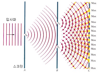
Young’s interference experiment is as follows: The light diffracted from the small holes S0 on-screen ‘A’ passes through the small holes S1 and S2.
Light passing through the two small holes overlaps between screens B and C, creating an interference fringe on screen C.
Constructive interference
When the waves arriving from the two slits are in the same phase, a bright pattern is formed.
To cause constructive interference, the path difference d·sin θ must be ‘0’ or an integer multiple of the wavelength.
d: Slit spacing (m)
θ: diffraction angle (rad)
λ: wavelength of light (m)
D: Distance from slit to screen (m)
When ‘n = 0’, the diffraction angle of the central axis ‘θ = 0’.
Destructive interference
When the waves arriving from the two slits are in the opposite phase, a dark pattern is formed
To cause destructive interference, the difference in the path between the two sources must be an odd multiple of the half wavelength.
d: Slit spacing (m)
θ: diffraction angle (rad)
λ: wavelength of light (m)
D: Distance from slit to screen (m)
The ‘n’ value above is used to number dark patterns caused by destructive interference.