DC-DC converters
Step-up and step-down circuits are types of DC-DC converters that convert an input voltage to a desired output voltage.
Step-up circuits convert a low input voltage to a higher output voltage, while step-down circuits convert a high input voltage to a lower output voltage. This conversion is typically accomplished using switching elements (e.g., MOSFETs), inductors, diodes, and capacitors.
Regulator
A regulator is a circuit that maintains a constant output voltage despite fluctuations in the input voltage. The goal of regulators is to achieve a very stable output voltage. In the past, linear (LDO) regulators, which converted excess voltage into heat energy, were widely used. However, current regulators utilize switching elements and inductors to minimize energy waste.
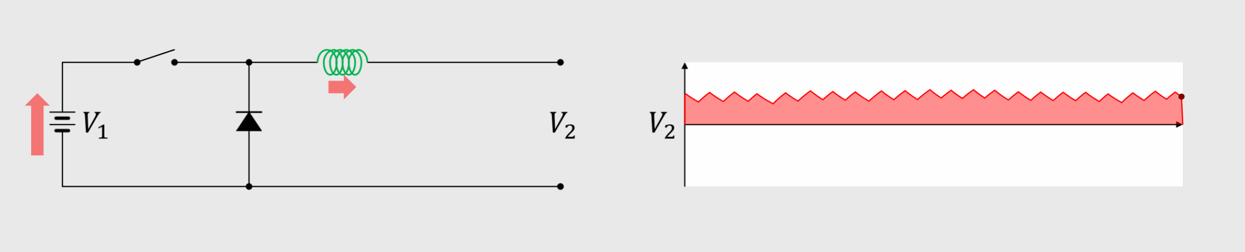
Step-down circuit
A step-down circuit consists of a switching element and an inductor, designed to lower the voltage. When the switching element generates a change in current, the inductor generates an electromotive force in the opposite direction, limiting the voltage fluctuation.
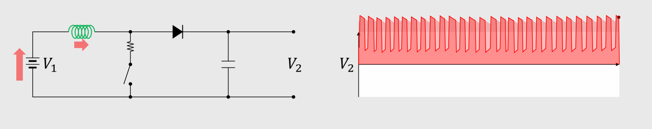
Step-up circuit
A step-up circuit is a circuit composed of a switching element and an inductor that increases voltage. The switching element causes the inductor to generate a forward electromotive force. This generates a higher voltage, in addition to the original voltage.

Because the voltage fluctuation is significant, a capacitor is connected as shown below to reduce it.
Step-up circuits may seem like they provide free energy because they increase voltage, but because they reduce current, the output power consumption cannot exceed the input. Furthermore, because additional energy is required to operate the converter, the gains and losses are negative when viewed solely in terms of energy.
Polarity reversal circuit
The electromotive force of an inductor can also be used to output a voltage with the opposite polarity of the input voltage. And a diode blocks forward voltage.
